What is the optical and geometric path of light. What is optical path length, optical path difference? Conditions for maximums and minimums during interference
Definition 1
Optics- one of the branches of physics that studies the properties and physical nature of light, as well as its interactions with substances.
This section is divided into three parts below:
- geometric or, as it is also called, ray optics, which is based on the concept of light rays, which is where its name comes from;
- wave optics, studies phenomena in which the wave properties of light are manifested;
- Quantum optics considers such interactions of light with substances in which the corpuscular properties of light make themselves known.
In the current chapter we will consider two subsections of optics. The corpuscular properties of light will be discussed in the fifth chapter.
Long before the understanding of the true physical nature of light arose, humanity already knew the basic laws of geometric optics.
Law of rectilinear propagation of light
Definition 1Law of rectilinear propagation of light states that in an optically homogeneous medium, light propagates in a straight line.
This is confirmed by the sharp shadows that are cast by opaque bodies when illuminated using a relatively small light source, that is, the so-called “point source”.
Another proof lies in a fairly well-known experiment on the passage of light from a distant source through a small hole, resulting in a narrow beam of light. This experience leads us to the idea of a light beam as a geometric line along which light propagates.
Definition 2
It is worth noting the fact that the very concept of a light ray, together with the law of rectilinear propagation of light, loses all its meaning if the light passes through holes whose dimensions are similar to the wavelength.
Based on this, geometric optics, which is based on the definition of light rays, is the limiting case of wave optics at λ → 0, the scope of which will be considered in the section on light diffraction.
At the interface between two transparent media, light can be partially reflected in such a way that some of the light energy will be dissipated after reflection in a new direction, while the other will cross the boundary and continue its propagation in the second medium.
Law of Light Reflection
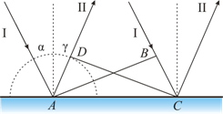
Definition 3Law of Light Reflection, is based on the fact that the incident and reflected rays, as well as the perpendicular to the interface between the two media, reconstructed at the point of incidence of the ray, are in the same plane (the plane of incidence). In this case, the angles of reflection and incidence, γ and α, respectively, are equal values.
Law of light refraction
Definition 4Law of light refraction, is based on the fact that the incident and refracted rays, as well as the perpendicular to the interface between two media, reconstructed at the point of incidence of the ray, lie in the same plane. The ratio of the sin angle of incidence α to the sin angle of refraction β is a value that is constant for the two given media:
sin α sin β = n .
The scientist W. Snell experimentally established the law of refraction in 1621.
Definition 5
Constant n – is the relative refractive index of the second medium relative to the first.
Definition 6
The refractive index of a medium relative to vacuum is called - absolute refractive index.
Definition 7
Relative refractive index of two media is the ratio of the absolute refractive indices of these media, i.e.:
The laws of refraction and reflection find their meaning in wave physics. Based on its definitions, refraction is the result of the transformation of the speed of wave propagation during the transition between two media.
Definition 8
Physical meaning of the refractive index is the ratio of the speed of wave propagation in the first medium υ 1 to the speed in the second υ 2:
Definition 9
The absolute refractive index is equivalent to the ratio of the speed of light in a vacuum c to the speed of light v in the medium:
In Figure 3. 1 . 1 illustrates the laws of reflection and refraction of light.
Figure 3. 1 . 1 . Laws of reflection υ refraction: γ = α; n 1 sin α = n 2 sin β.
Definition 10
A medium whose absolute refractive index is smaller is optically less dense.
Definition 11
Under conditions of light transition from one medium inferior in optical density to another (n 2< n 1) мы получаем возможность наблюдать явление исчезновения преломленного луча.
This phenomenon can be observed at angles of incidence that exceed a certain critical angle α p r. This angle is called the limiting angle of total internal reflection (see Fig. 3, 1, 2).
For the angle of incidence α = α p sin β = 1 ; value sin α p p = n 2 n 1< 1 .
Provided that the second medium is air (n 2 ≈ 1), then the equality can be rewritten as: sin α p p = 1 n, where n = n 1 > 1 is the absolute refractive index of the first medium.
Under the conditions of the glass-air interface, where n = 1.5, the critical angle is α p p = 42 °, while for the water-air interface n = 1. 33, and α p p = 48 , 7 ° .

Figure 3. 1 . 2. Total internal reflection of light at the water-air interface; S – point light source.
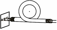
The phenomenon of total internal reflection is widely used in many optical devices. One of such devices is a fiber light guide - thin, randomly curved threads made of optically transparent material, inside of which light entering the end can spread over enormous distances. This invention became possible only thanks to the correct application of the phenomenon of total internal reflection from lateral surfaces (Fig. 3. 1. 3).
Definition 12
Fiber optics is a scientific and technical direction based on the development and use of optical fibers.

Drawing 3 . 1 . 3 . Propagation of light in a fiber light guide. When the fiber is strongly bent, the law of total internal reflection is violated, and light partially exits the fiber through the side surface.

Drawing 3 . 1 . 4 . Model of reflection and refraction of light.
If you notice an error in the text, please highlight it and press Ctrl+Enter
OPTICAL PATH LENGTH is the product of the path length of a light beam and the refractive index of the medium (the path that light would travel during the same time, propagating in a vacuum).
Calculation of the interference pattern from two sources.
Calculation of the interference pattern from two coherent sources.
Let's consider two coherent light waves emanating from sources u (Fig. 1.11.).

The screen for observing the interference pattern (alternating light and dark stripes) will be placed parallel to both slits at the same distance. Let us denote x as the distance from the center of the interference pattern to the point P under study on the screen.
Let us denote the distance between the sources as d. The sources are located symmetrically relative to the center of the interference pattern. From the figure it is clear that

Hence
and the optical path difference is equal to
![]()
The path difference is several wavelengths and is always significantly smaller, so we can assume that Then the expression for the optical path difference will have the following form:
Since the distance from the sources to the screen is many times greater than the distance from the center of the interference pattern to the observation point, we can assume that. e.
Substituting value (1.95) into condition (1.92) and expressing x, we obtain that intensity maxima will be observed at values
![]() , (1.96)
, (1.96)
where is the wavelength in the medium, and m is the order of interference, and X max - coordinates of intensity maxima.
Substituting (1.95) into condition (1.93), we obtain the coordinates of the intensity minima
![]() , (1.97)
, (1.97)
An interference pattern will be visible on the screen, which looks like alternating light and dark stripes. The color of the light stripes is determined by the filter used in the installation.
The distance between adjacent minima (or maxima) is called the interference fringe width. From (1.96) and (1.97) it follows that these distances have the same value. To calculate the width of the interference fringe, you need to subtract the coordinate of the adjacent maximum from the coordinate value of one maximum
For these purposes, you can also use the coordinate values of any two adjacent minima.
Coordinates of intensity minima and maxima.
Optical length of ray paths. Conditions for obtaining interference maxima and minima.
In a vacuum, the speed of light is equal to , in a medium with a refractive index n the speed of light v becomes less and is determined by the relation (1.52)
The wavelength in vacuum, and in a medium, is n times less than in vacuum (1.54):
When moving from one medium to another, the frequency of light does not change, since secondary electromagnetic waves emitted by charged particles in the medium are the result of forced oscillations occurring at the frequency of the incident wave.
Let two point coherent light sources emit monochromatic light (Fig. 1.11). For them, the coherence conditions must be satisfied: To point P, the first ray travels in a medium with a refractive index - a path, the second ray passes in a medium with a refractive index - a path. The distances from the sources to the observed point are called the geometric lengths of the ray paths. The product of the refractive index of the medium and the geometric path length is called the optical path length L=ns. L 1 = and L 1 = are the optical lengths of the first and second paths, respectively.
Let u be the phase velocities of the waves.
The first ray will excite an oscillation at point P:
 , (1.87)
and the second ray is vibration
 , (1.88)
The phase difference between the oscillations excited by the rays at point P will be equal to:
 , (1.89)
The multiplier is equal to (- wavelength in vacuum), and the expression for the phase difference can be given the form
there is a quantity called the optical path difference. When calculating interference patterns, it is the optical difference in the path of the rays that should be taken into account, i.e., the refractive indices of the media in which the rays propagate.
From formula (1.90) it is clear that if the optical path difference is equal to an integer number of wavelengths in vacuum
then the phase difference and oscillations will occur with the same phase. Number m is called the order of interference. Consequently, condition (1.92) is the condition of the interference maximum.
If equal to half an integer number of wavelengths in vacuum,
![]() , (1.93)
, (1.93)
That ![]() , so that the oscillations at point P are in antiphase. Condition (1.93) is the condition of the interference minimum.
, so that the oscillations at point P are in antiphase. Condition (1.93) is the condition of the interference minimum.
So, if at a length equal to the optical path difference of the rays, an even number of half-wavelengths fits, then a maximum intensity is observed at a given point on the screen. If there is an odd number of half-wavelengths along the length of the optical ray path difference, then a minimum illumination is observed at a given point on the screen.
Recall that if two ray paths are optically equivalent, they are called tautochronous. Optical systems - lenses, mirrors - satisfy the condition of tautochronism.
The basic laws of geometric optics have been known since ancient times. Thus, Plato (430 BC) established the law of rectilinear propagation of light. Euclid's treatises formulated the law of rectilinear propagation of light and the law of equality of angles of incidence and reflection. Aristotle and Ptolemy studied the refraction of light. But the exact wording of these laws of geometric optics Greek philosophers could not find it. Geometric optics is the limiting case of wave optics, when the wavelength of light tends to zero. The simplest optical phenomena, such as the appearance of shadows and obtaining images in optical instruments, can be understood within the framework of geometric optics.
The formal construction of geometric optics is based on four laws established experimentally: · the law of rectilinear propagation of light; · the law of independence of light rays; · the law of reflection; · the law of refraction of light. To analyze these laws, H. Huygens proposed a simple and visual method, later called Huygens' principle .Each point to which light excitation reaches is ,in its turn, center of secondary waves;the surface that envelops these secondary waves at a certain moment in time indicates the position of the front of the actually propagating wave at that moment.
Based on his method, Huygens explained straightness of light propagation and brought out laws of reflection And refraction .Law of rectilinear propagation of light :· light propagates rectilinearly in an optically homogeneous medium.Proof of this law is the presence of shadows with sharp boundaries from opaque objects when illuminated by small sources. Careful experiments have shown, however, that this law is violated if light passes through very small holes, and the deviation from straightness of propagation is greater, the smaller the holes .

The shadow cast by an object is determined by straightness of light rays in optically homogeneous media. Fig 7.1 Astronomical illustration rectilinear propagation of light and, in particular, the formation of umbra and penumbra can be caused by the shading of some planets by others, for example lunar eclipse , when the Moon falls into the Earth's shadow (Fig. 7.1). Due to the mutual movement of the Moon and the Earth, the shadow of the Earth moves across the surface of the Moon, and the lunar eclipse passes through several partial phases (Fig. 7.2).
Law of independence of light beams :· the effect produced by an individual beam does not depend on whether,whether other bundles act simultaneously or whether they are eliminated. By dividing the light flux into separate light beams (for example, using diaphragms), it can be shown that the action of the selected light beams is independent. Law of Reflection (Fig. 7.3): the reflected ray lies in the same plane as the incident ray and the perpendicular,drawn to the interface between two media at the point of impact;· angle of incidenceα equal to angle reflectionsγ: α = γ

To derive the law of reflection Let's use Huygens' principle. Let us assume that a plane wave (wave front AB With, falls on the interface between two media (Fig. 7.4). When the wave front AB will reach the reflecting surface at the point A, this point will begin to radiate secondary wave .· For the wave to travel a distance Sun time required Δ t = B.C./ υ . During the same time, the front of the secondary wave will reach the points of the hemisphere, the radius AD which is equal to: υ Δ t= sun. The position of the reflected wave front at this moment in time, in accordance with Huygens’ principle, is given by the plane DC, and the direction of propagation of this wave is ray II. From the equality of triangles ABC And ADC flows out law of reflection: angle of incidenceα equal to the angle of reflection γ . Law of refraction (Snell's law) (Fig. 7.5): the incident ray, the refracted ray and the perpendicular drawn to the interface at the point of incidence lie in the same plane;· the ratio of the sine of the angle of incidence to the sine of the angle of refraction is a constant value for given media.


Derivation of the law of refraction. Let us assume that a plane wave (wave front AB), propagating in vacuum along direction I with speed With, falls on the interface with the medium in which the speed of its propagation is equal to u(Fig. 7.6). Let the time taken by the wave to travel the path Sun, equal to D t. Then BC = s D t. During the same time, the front of the wave excited by the point A in an environment with speed u, will reach points of the hemisphere whose radius AD = u D t. The position of the refracted wave front at this moment in time, in accordance with Huygens’ principle, is given by the plane DC, and the direction of its propagation - by ray III . From Fig. 7.6 it is clear that, i.e. .This implies Snell's law : A slightly different formulation of the law of propagation of light was given by the French mathematician and physicist P. Fermat.
Physical research relates mostly to optics, where he established in 1662 the basic principle of geometric optics (Fermat's principle). The analogy between Fermat's principle and the variational principles of mechanics played a significant role in the development of modern dynamics and the theory of optical instruments. According to Fermat's principle
, light propagates between two points along a path that requires least time.
Let us show the application of this principle to solving the same problem of light refraction. Ray from a light source S located in a vacuum goes to the point IN, located in some medium beyond the interface (Fig. 7.7). 
In every environment the shortest path will be straight S.A. And AB. Full stop A characterize by distance x from the perpendicular dropped from the source to the interface. Let's determine the time spent on traveling the path SAB:![]() .To find the minimum, we find the first derivative of τ with respect to X and equate it to zero: , from here we come to the same expression that was obtained based on Huygens’ principle: Fermat’s principle has retained its significance to this day and served as the basis for the general formulation of the laws of mechanics (including the theory of relativity and quantum mechanics). From Fermat's principle has several consequences. Reversibility of light rays
: if you reverse the beam III (Fig. 7.7), causing it to fall onto the interface at an angleβ, then the refracted ray in the first medium will propagate at an angle α, i.e. it will go in the opposite direction along the beam I .
Another example is a mirage
, which is often observed by travelers on hot roads. They see an oasis ahead, but when they get there, there is sand all around. The essence is that in this case we see light passing over the sand. The air is very hot above the road itself, and in the upper layers it is colder. Hot air, expanding, becomes more rarefied and the speed of light in it is greater than in cold air. Therefore, light does not travel in a straight line, but along a trajectory with the shortest time, turning into warm layers of air. If light comes from high refractive index media
(optically more dense) into a medium with a lower refractive index
(optically less dense) ( > ) ,
for example, from glass into air, then, according to the law of refraction, the refracted ray moves away from the normal
and the angle of refraction β is greater than the angle of incidence α (Fig. 7.8 A).
.To find the minimum, we find the first derivative of τ with respect to X and equate it to zero: , from here we come to the same expression that was obtained based on Huygens’ principle: Fermat’s principle has retained its significance to this day and served as the basis for the general formulation of the laws of mechanics (including the theory of relativity and quantum mechanics). From Fermat's principle has several consequences. Reversibility of light rays
: if you reverse the beam III (Fig. 7.7), causing it to fall onto the interface at an angleβ, then the refracted ray in the first medium will propagate at an angle α, i.e. it will go in the opposite direction along the beam I .
Another example is a mirage
, which is often observed by travelers on hot roads. They see an oasis ahead, but when they get there, there is sand all around. The essence is that in this case we see light passing over the sand. The air is very hot above the road itself, and in the upper layers it is colder. Hot air, expanding, becomes more rarefied and the speed of light in it is greater than in cold air. Therefore, light does not travel in a straight line, but along a trajectory with the shortest time, turning into warm layers of air. If light comes from high refractive index media
(optically more dense) into a medium with a lower refractive index
(optically less dense) ( > ) ,
for example, from glass into air, then, according to the law of refraction, the refracted ray moves away from the normal
and the angle of refraction β is greater than the angle of incidence α (Fig. 7.8 A).

As the angle of incidence increases, the angle of refraction increases (Fig. 7.8 b, V), until at a certain angle of incidence () the angle of refraction is equal to π/2. The angle is called limit angle
. At angles of incidence α >
all incident light is completely reflected (Fig. 7.8 G).
· As the angle of incidence approaches the limiting one, the intensity of the refracted ray decreases, and the reflected ray increases. · If , then the intensity of the refracted ray becomes zero, and the intensity of the reflected ray is equal to the intensity of the incident one (Fig. 7.8 G).
· Thus,at angles of incidence ranging from to π/2,the beam is not refracted,and is fully reflected on the first Wednesday,Moreover, the intensities of the reflected and incident rays are the same. This phenomenon is called complete reflection.
The limit angle is determined from the formula: ![]() ;
;![]() .The phenomenon of total reflection is used in total reflection prisms
(Fig. 7.9).
.The phenomenon of total reflection is used in total reflection prisms
(Fig. 7.9). 
The refractive index of glass is n » 1.5, therefore the limiting angle for the glass-air interface = arcsin (1/1.5) = 42°. When light falls on the glass-air boundary at α > 42° there will always be total reflection. In Fig. Figure 7.9 shows total reflection prisms that allow: a) to rotate the beam by 90°; b) rotate the image; c) wrap the rays. Total reflection prisms are used in optical instruments (for example, in binoculars, periscopes), as well as in refractometers that make it possible to determine the refractive index of bodies (according to the law of refraction, by measuring , we determine the relative refractive index of two media, as well as the absolute refractive index of one of the media, if the refractive index of the second medium is known).
The phenomenon of total reflection is also used in light guides , which are thin, randomly curved threads (fibers) made of optically transparent material. Fig. 7.10 In fiber parts, glass fiber is used, the light-guiding core (core) of which is surrounded by glass - a shell made of another glass with a lower refractive index. Light incident on the end of the light guide at angles greater than the limit , undergoes at the core-shell interface total reflection and propagates only along the light guide core. Light guides are used to create high-capacity telegraph-telephone cables . The cable consists of hundreds and thousands of optical fibers as thin as human hair. Through such a cable, the thickness of an ordinary pencil, up to eighty thousand telephone conversations can be simultaneously transmitted. In addition, light guides are used in fiber-optic cathode ray tubes, in electronic counting machines, for encoding information, in medicine (for example, stomach diagnostics), for purposes of integrated optics.
MINIMUM LIST OF EXAM QUESTIONS IN PHYSICS (SECTION “OPTICS, ELEMENTS OF ATOMIC AND NUCLEAR PHYSICS”) FOR CORRESPONDENTS
1. Light radiation and its characteristics
Light is a material object with a dual nature (wave-particle duality). In some phenomena, light behaves like electromagnetic wave(the process of oscillations of electric and magnetic fields spreading in space), in others - as a stream of special particles - photons or quanta of light.
In an electromagnetic wave, the voltage vector electric field E, magnetic field H and wave propagation speed V are mutually perpendicular and form a right-handed system.
Vectors E and H oscillate in the same phase. The condition for the wave is:
When a light wave interacts with matter, the electrical component of the wave plays the greatest role (the magnetic component in non-magnetic media has a weaker effect), therefore vector E (the electric field strength of the wave) is called light vector and its amplitude is denoted by A.
A characteristic of the energy transfer of a light wave is intensity I - this is the amount of energy transferred per unit time by a light wave through a unit area perpendicular to the direction of propagation of the wave. The line along which the wave energy travels is called a ray.
2. Reflection and refraction of a plane wave at the boundary of 2 dielectrics. Laws of reflection and refraction of light.
Law of Light Reflection: incident ray, reflected ray and normal to the interface
the media at the point of impact lie in the same plane. The angle of incidence is equal to the angle of reflection (α = β). Moreover, the incident and reflected rays lie on opposite sides of the normal.
Law of light refraction: the incident beam, the refracted beam and the normal to the interface at the point of incidence lie in the same plane. The ratio of the sine of the angle of incidence to the sine of the angle of refraction is a constant value for these two media and is called the relative refractive index or the refractive index of the second medium relative to the first.
sin α / sin γ = n21 = n2 / n1

where n 21 is the relative refractive index of the second medium relative to the first,
n 1, n 2 - absolute refractive indices the first and second media (i.e., the refractive indices of the media relative to vacuum).
A medium with a higher refractive index is called optically more dense. When a beam falls from an optically less dense medium into an optically denser medium (n2 >n1)
the angle of incidence is greater than the angle of refraction α>γ (as in the figure).
When the beam falls from an optically more dense medium to an optically less dense medium (n 1 > n 2 ) the angle of incidence is less than the angle of refraction α< γ . At a certain angle of incidence
the refracted ray will be sliding towards the surface (γ =90о). For angles greater than this angle, the incident ray is completely reflected from the surface ( phenomenon of total internal reflection).
Relative n21 |
and the absolute refractive indices of media n1 and n2 can be |
|||||||||
also express in terms of the speed of light in media |
||||||||||
n 21 = |
n 1 = |
Where c is the speed of light in vacuum. |
||||||||
3. Coherence. Interference of light waves. Interference pattern from two sources.
Coherence is the coordinated penetration of two or more oscillatory processes. Coherent waves when added create an interference pattern. Interference is the process of addition of coherent waves, which consists in the redistribution of the energy of a light wave in space, which is observed in the form of dark and light stripes.
The reason for the lack of observation of interference in life is the incoherence of natural light sources. The radiation of such sources is formed by a combination of radiation from individual atoms, each of which emits a “snip” of a harmonic wave, which is called a train, within ~10-8 s.
Coherent waves from real sources can be obtained by separating the wave of one source into two or more, then, allowing them to go through different optical paths, bring them together at one point on the screen. An example is Jung's experience.

Optical path length of light wave
L = nl,
where l is the geometric path length of a light wave in a medium with refractive index n.
Optical path difference between two light waves
∆ = L 1 −L 2 .
Condition for amplification of light (maxima) during interference
∆ = ± k λ, where k=0, 1, 2, 3, λ - light wavelength.
Light attenuation condition (minimums)
∆ = ± (2 k + 1) λ 2, where k=0, 1, 2, 3……
Distance between two interference fringes created by two coherent light sources on a screen located parallel to two coherent light sources
∆y = d L λ ,
where L is the distance from the light sources to the screen, d is the distance between the sources
(d< 4. Interference in thin films. Strips of equal thickness, equal inclination, Newton's ring. Optical difference in the path of light waves that occurs when monochromatic light is reflected from a thin film ∆ = 2 dn 2 −sin 2 i ± λ 2 or ∆ = 2 dn cos r ± λ 2 where d is the film thickness; n is the refractive index of the film; i - angle of incidence; r is the angle of refraction of light in the film. If we fix the angle of incidence i and take a film of variable thickness, then for certain areas with thickness d interference fringes of equal thickness. These stripes can be obtained by shining a parallel beam of light onto a plate with different thicknesses in different places. If a diverging beam of rays is directed at a plane-parallel plate (d = const) (i.e., a beam that will provide different angles of incidence i), then when rays incident at certain identical angles are superimposed, interference fringes will be observed, which are called stripes of equal slope A classic example of strips of equal thickness is Newton's rings. They are formed if a monochromatic beam of light is directed onto a plano-convex lens lying on a glass plate. Newton's rings are interference fringes from regions of equal thickness of the air gap between the lens and the plate. Radius of Newton's light rings in reflected light where k =1, 2, 3…… - ring number; R - radius of curvature. Radius of Newton's dark rings in reflected light r k = kR λ, where k =0, 1, 2, 3……. 5. Coating of optics Coating of optics consists of applying a thin transparent film to the surface of the glass part, which, due to interference, eliminates the reflection of the incident light, thus increasing the aperture of the device. Refractive index antireflection film n must be less than the refractive index of the glass part n about . The thickness of this antireflective film is found from the condition of attenuation of light during interference according to the formula d min = 4 λ n 6. Diffraction of light. Huygens-Fresnel principle. Fresnel diffraction. Fresnel zone method. Vector diagram of Fresnel zones. Fresnel diffraction on the simplest obstacles (round hole). Light diffraction is a set of phenomena consisting in the redistribution of light flux during the passage of a light wave in media with sharp inhomogeneities. In a narrow sense, diffraction is the bending of waves around obstacles. Diffraction of light leads to violation of the laws of geometric optics, in particular, the laws of rectilinear propagation of light. There is no fundamental difference between diffraction and interference, because both phenomena lead to a redistribution of light wave energy in space. A distinction is made between Fraunhofer diffraction and Fresnel diffraction. Fraunhofer diffraction– diffraction in parallel rays. Observed when the screen or viewing point is located far from the obstacle. Fresnel diffraction- This is diffraction in converging rays. Observed at a close distance from an obstacle. The phenomenon of diffraction is explained qualitatively Huygens' principle: Each point on the wave front becomes a source of secondary spherical waves, and the new wave front represents the envelope of these secondary waves. Fresnel supplemented Huygens' principle with the idea of coherence and interference of these secondary waves, which made it possible to calculate the wave intensity for different directions. Principle Huygens-Fresnel: Each point on the wave front becomes a source of coherent secondary spherical waves, and a new wave front is formed as a result of the interference of these waves. Fresnel proposed dividing symmetrical wave surfaces into special zones, the distances from the boundaries of which to the observation point differ by λ/2. Adjacent zones act in antiphase, i.e. amplitudes generated by adjacent zones at the observation point are subtracted. To find the amplitude of a light wave, the Fresnel zone method uses the algebraic addition of the amplitudes created at this point by the Fresnel zones. Radius of the outer boundary of the m-th annular Fresnel zone for a spherical wave surface r m = m a ab + b λ , where a is the distance from the light source to the wave surface, b is the distance from the wave surface to the observation point. Fresnel zone vector diagram is a spiral. Using a vector diagram makes it easier to find the amplitude of the resulting oscillation electric field strength of wave A (and, accordingly, intensity I ~A 2 ) in the center of the diffraction pattern when a light wave is diffraction on various obstacles. The resulting vector A from all Fresnel zones is the vector connecting the beginning and end of the spiral. During Fresnel diffraction, a dark spot (minimum intensity) will be observed at a round hole in the center of the diffraction pattern if an even number of Fresnel zones fits in the hole. The maximum (light spot) is observed if an odd number of zones are placed in the hole. 7.
Fraunhofer diffraction by a slit. The angle ϕ of deflection of the rays (diffraction angle), corresponding to the maximum (light stripe) during diffraction by one narrow slit, is determined from the condition b sin ϕ = (2 k + 1) λ 2, where k= 1, 2, 3,..., The angle ϕ of deflection of the rays, corresponding to the minimum (dark band) during diffraction by a narrow slit, is determined from the condition b sin ϕ = k λ , where k= 1, 2, 3,..., where b is the slot width; k is the ordinal number of the maximum. The dependence of intensity I on the diffraction angle ϕ for a slit has the form 8.
Fraunhofer diffraction by a diffraction grating. One-dimensional diffraction grating is a system of periodically located transparent and opaque to light areas. The transparent area is a slot of width b. Opaque areas are slits with width a. The quantity a+b=d is called the period (constant) of the diffraction grating. A diffraction grating splits the light wave incident on it into N coherent waves (N is the total number of targets in the grating). The diffraction pattern is the result of the superposition of the diffraction patterns from all the individual slits. IN directions in which the waves from the slits reinforce each other are observedmajor highs. IN in directions in which none of the slits sends light (minima are observed for the slits), absolute minima are formed. IN directions where waves from neighboring slits “quench” each other, it is observed secondary minima. Between secondary minima there are weak secondary highs. The dependence of intensity I on the diffraction angle ϕ for a diffraction grating has the form − 7 λ − 5 λ − 4 λ − 4 λ 5 λ d d λ − b Angle ϕ of ray deflection corresponding to main maximum(light stripe) when light is diffraction on a diffraction grating, determined from the condition d sin ϕ = ± m λ , where m= 0, 1, 2, 3,..., where d is the period of the diffraction grating, m is the ordinal number of the maximum (spectrum order). 9.
Diffraction by spatial structures. Wulff-Bragg formula. The Wulff-Bragg formula describes the diffraction of X-rays by crystals with a periodic arrangement of atoms in three dimensions From (4) it follows that the result of the addition of two coherent light rays depends on both the path difference and the light wavelength. The wavelength in vacuum is determined by the quantity , where With=310 8 m/s is the speed of light in vacuum, and The frequency of light vibrations determines color light wave. When moving from one environment to another, the color does not change. This means that the frequency of light vibrations in all media is the same. But then, when light passes, for example, from a vacuum into a medium with a refractive index n the wavelength must change where 0 is the wavelength in vacuum. That is, when light passes from a vacuum into an optically denser medium, the wavelength of the light is decreases V n once. On the geometric path Magnitude Optical path length In other words (see relation (5)): The optical path length of light in a substance is numerically equal to the path length in a vacuum, on which the same number of light waves fits as on the geometric length in the substance. Because the result of interference depends on phase shift between interfering light waves, then it is necessary to evaluate the result of interference optical path difference between two rays which contains the same number of waves regardless on the optical density of the medium. The division of light beams into “halves” and the appearance of an interference pattern is also possible under natural conditions. A natural “device” for dividing light beams into “halves” are, for example, thin films. Figure 5 shows a thin transparent film with a thickness ki at the angle of refraction The speed of light in air is almost equal to the speed of light in vacuum. Therefore, the optical density of air can be taken as unity. If the optical density of the film material
n, then the optical path length of the refracted ray in the film ABCn. In addition, when beam 1 is reflected from an optically denser medium, the phase of the wave changes to the opposite, that is, half a wave is lost (or vice versa, gained). Thus, the optical path difference of these rays should be written in the form wholesale .
=
ABCn
–
AD / . (6) From the figure it is clear that ABC
= 2d/cos r, A AD = ACsin i
= 2dtg rsin i. If we put the optical density of air n V=1, then known from the school course Snell's law gives for the refractive index (optical density of the film) the dependence
Substituting all this into (6), after transformations we obtain the following relation for the optical path difference of the interfering rays: Because When beam 1 is reflected from the film, the phase of the wave changes to the opposite, then conditions (4) for the maximum and minimum interference are reversed:
- condition max - condition min.
(8)


 – frequency of light vibrations. The speed of light v in any optically transparent medium is always less than the speed of light in vacuum and the ratio
  called optical density environment. This value is numerically equal to the absolute refractive index of the medium.
 , which can be converted like this:
 ,
, in an environment with optical density n will fit
 waves (5)
 called optical path length light in matter:
 light in a substance is the product of its geometric path length in this medium and the optical density of the medium:
 .
. ,
,
2.1.3.Interference in thin films
 , to which at an angle
  A beam of parallel light rays falls (a plane electromagnetic wave). Beam 1 is partially reflected from the upper surface of the film (beam 1), and partially refracted into the film
 . The refracted beam is partially reflected from the lower surface and exits the film parallel to beam 1 (beam 2). If these rays are directed at a collecting lens L, then on the screen E (in the focal plane of the lens) they will interfere. The result of interference will depend on optical the difference in the path of these rays from the “division” point
  to the meeting point
  . From the figure it is clear that geometric the difference in the path of these rays is equal to the difference geom . =ABC–AD.
 . (6a)

It can be shown that when passing light through a thin film also produces an interference pattern. In this case, there will be no loss of half a wave, and conditions (4) are met.
Thus, the conditions max And min upon interference of rays reflected from a thin film, are determined by relation (7) between four parameters -  It follows that:
1) in “complex” (non-monochromatic) light, the film will be painted with the color whose wavelength  satisfies the condition max;
2) changing the inclination of the rays (  ), you can change the conditions max, making the film either dark or light, and by illuminating the film with a diverging beam of light rays, you can get stripes« equal slope", corresponding to the condition max by angle of incidence
  ;
;
3) if the film has different thicknesses in different places (  ), then it will be visible strips of equal thickness, on which the conditions are met max by thickness
  ;
;
4) under certain conditions (conditions min when the rays are incident vertically on the film), the light reflected from the surfaces of the film will cancel each other out, and reflections there won't be any from the film.
